MPU-6050 가속도/자이로 센서
아래 링크를 참조했다.
MPU-6050 가속도/자이로 센서 제어 (아두이노) — Steemit
MPU-6050 가속도/자이로 센서 제어 (아두이노) 오늘은 MPU-6050 가속도/자이로 센서를 이용하여 실험하는 시간을 갖도록 하겠습니다. 자이로 센서를 사용하려면 오일러의 공식을 알아야 하고 오일러
steemit.com
MPU-6050 모듈은 가속도/자이로를 측정할 수 있는 센서이다.
가속도는 지구 중력을 기준으로 x, y, z 축의 가속도 크기를 구할 수 있으면 자이로(각속도)는 시간당 x, y, z 축의 회전속도 속도를 구할 수 있다.

MPU-6050 모듈에서 측정된 값은 바로 회전각으로 이해하기 힘들다. 그래서 계산이 필요하는 데 오일러의 각 공식을 알아야 하며, 아래 링크된 위키백과사전을 참고한다.
오일러 각 - 위키백과, 우리 모두의 백과사전
위키백과, 우리 모두의 백과사전. 오일러 각(Euler角, Euler angle)은 강체가 놓인 방향을 3차원 공간에 표시하기 위해 레온하르트 오일러가 도입한 세 개의 각도이다.[1] 즉, 3차원 회전군 SO(3)의 한 좌
ko.wikipedia.org
3차원 회전 좌표계로 X축 회전을 롤, Y축 회전을 피치, Z축 회전을 요라고 한다.. 롤, 피치, 요에 대한 계산 공식이 따로 있다.
상보필 터과 칼만필터는 회전각을 구할 때 필요한 필터이다.
아래는 상보필터의 공식이다다.
- angle = 0.98*(angle+자이로값*dt)+0.02*(가속도값) [angle-출력각, dt-적분할 시간]
출처 : http://mechasolutionwiki.com/index.php?title=%EC%83%81%EB%B3%B4%ED%95%84%ED%84%B0
칼만필터은 아래 위키백과에 가셔서 공식을 살펴보시기 바랍니다.
https://ko.wikipedia.org/wiki/%EC%B9%BC%EB%A7%8C_%ED%95%84%ED%84%B0
아래 MPU-6050 데이터 시트에 가셔서 MPU-6050에 대해서 알아두시기 바랍니다.
https://www.invensense.com/wp-content/uploads/2015/02/MPU-6000-Datasheet1.pdf
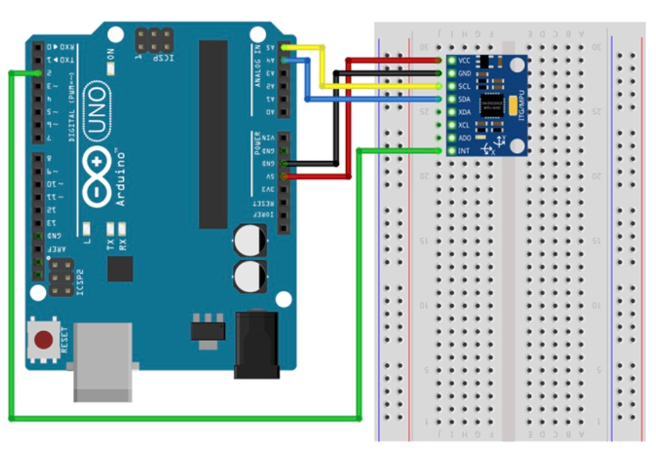
MPU-6050 가속도/자이로 센서 구조
MPU-6050 모듈은 가속도 (x, y, z)와 자이로(각속도) (x, y, z)의 값과 온도 값을 얻을 수 있다.
MPU-6050 모듈은 I2C 통신으로 14개의 레지지스터 값을 아두이노로 보내고 데이터는 16bit로 구성된 총 7개의 데이터를 얻게 된다.
| Arduino | MCU-6050 | 설명 |
| 5V | VCC | 전원 담당 |
| GND | GND | 전원 담당 |
| A5 | SCL | I2C 통신 |
| A4 | SDA | I2C 통신 |
| XDA | 하위 I2C 통신 | |
| XCL | 하위 I2C 통신 | |
| ADO | 주소 | |
| 2 Pin(Interrupt Pin) | INT | 인터럽트핀 |
MPU-6050 모듈의 핀에 대해서 위 표를 잘 보면 인터럽트핀은 아두이노우노의 경우는 인터럽트 핀이 2번이기에 사용할 경우 2번 핀에 연결하시면 되고 사용하는 아두이노보드에 따라 해당 I2C핀과 인터럽트 핀에 맞게 연결하시면 된다.
MPU-6050 라이브러리 추가하기
MPU-6050을 사용하기 위해 아두이노 라이브러리를 총 2개 추가해야 한다.
아래 링크를 클릭하여 ' MPU6050_ibrary와 12 Cdev_library' 압축파일을 다운로드한다.
위의 라이브러리리의 이름에서 _libraty를 지우고 아두이노 파일 위치에 찾아서 저장한다.
이때 위치나 이름이 틀리면 라이브러리가 정상적으로 작동하지 않는다.
MPU-6050 가속도/자이로 회로도
코드
[ 값 출력 확인 ]
- 참고 소스 출처 : https://playground.arduino.cc/Main/MPU-6050
우선 기본 라이브러리 없이 순수 MPU-6050 모듈에서 측정되는 값이 어떤 값들이 출력되는지 살펴보도록 한다.
위 링크된 MPU-6050 소스에 대해 간단히 살펴보겠다.
#include<Wire.h>
const int MPU_addr=0x68; // I2C address of the MPU-6050
int16_t AcX,AcY,AcZ,Tmp,GyX,GyY,GyZ;
void setup(){
Wire.begin();
Wire.beginTransmission(MPU_addr);
Wire.write(0x6B); // PWR_MGMT_1 register
Wire.write(0); // set to zero (wakes up the MPU-6050)
Wire.endTransmission(true);
Serial.begin(9600);
}
void loop(){
Wire.beginTransmission(MPU_addr);
Wire.write(0x3B); // starting with register 0x3B (ACCEL_XOUT_H)
Wire.endTransmission(false);
Wire.requestFrom(MPU_addr,14,true); // request a total of 14 registers
AcX=Wire.read()<<8|Wire.read(); // 0x3B (ACCEL_XOUT_H) & 0x3C (ACCEL_XOUT_L)
AcY=Wire.read()<<8|Wire.read(); // 0x3D (ACCEL_YOUT_H) & 0x3E (ACCEL_YOUT_L)
AcZ=Wire.read()<<8|Wire.read(); // 0x3F (ACCEL_ZOUT_H) & 0x40 (ACCEL_ZOUT_L)
Tmp=Wire.read()<<8|Wire.read(); // 0x41 (TEMP_OUT_H) & 0x42 (TEMP_OUT_L)
GyX=Wire.read()<<8|Wire.read(); // 0x43 (GYRO_XOUT_H) & 0x44 (GYRO_XOUT_L)
GyY=Wire.read()<<8|Wire.read(); // 0x45 (GYRO_YOUT_H) & 0x46 (GYRO_YOUT_L)
GyZ=Wire.read()<<8|Wire.read(); // 0x47 (GYRO_ZOUT_H) & 0x48 (GYRO_ZOUT_L)
Serial.print("AcX = "); Serial.print(AcX);
Serial.print(" | AcY = "); Serial.print(AcY);
Serial.print(" | AcZ = "); Serial.print(AcZ);
Serial.print(" | Tmp = "); Serial.print(Tmp/340.00+36.53); //equation for temperature in degrees C from datasheet
Serial.print(" | GyX = "); Serial.print(GyX);
Serial.print(" | GyY = "); Serial.print(GyY);
Serial.print(" | GyZ = "); Serial.println(GyZ);
delay(333);
}MPU-6050의 I2C 주소는 '0x6 B'이다.
| int16_t AcX,AcY,AcZ,Tmp,GyX,GyY,GyZ; |
16bit int형 자료형으로 가속도 3개, 온도 1개, 자이로 3개의 변수를 선언한다.
| Wire.beginTransmission(MPU_addr); Wire.write(0x6B); // PWR_MGMT_1 register Wire.write(0); // set to zero (wakes up the MPU-6050) Wire.endTransmission(true); |
beginTransmission() 함수로 '0x6 B'주소로 I2C 슬레이브 디바이스로 전송을 시작합니다. 그리고 버스가 연결되면 '0x6B' 보내고 다시 '0'을 보내고 나서 endTransmission(true)함수로 버스를 해제하는 메세지를 보냅니다. 초기화 수행합니다.
Wire.beginTransmission(MPU_addr); //MPU-6050 '0x6B'주소 시작
Wire.write(0x3 B); // 0x3B 읽을 rigister주소
Wire.endTransmission(false) //버스를 연결 활성화
Wire.requestFrom(MPU_addr,14, true) //데이터 요청하는데 14 레지스터 값을 요청
이렇게 해서, Wire.read() 함수를 이용해서 실제로 MPU-6050에서 값을 읽게 된다. 0x3 B~0x48의 레지스터값을 읽어와서 가속도, 온도, 자이로 값을 만들어 내게 된다.
| Wire.read()<<8|Wire.read(); |
'0x3 B' 레지스터 값을 왼쪽으로 8bit 이동시키고 '0x3 C' 레지스터 값을 비트 OR 연산을 수행한다. 이 식을 통해서 2개의 레지스터 값을 합치게 된다.
예를 들어 임의의 값 A, B가 있을 때 위 식으로 계산한다면
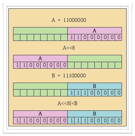
더 쉽게 살펴보면은, 비트 OR 연산은 둘 중 하나가 1이면 결과가 1이 나오는 연산이다.
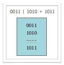
이렇게 14개의 레지스트값을 2개씩 이 수식을 통해서 가속도(x, y, z), 온도, 자이로(x, y, z) 값을 순차적으로 Wire.read() 함수를 14번 읽어서 연산을 수행하여 값을 얻게 됩니다. 그 값을 시리얼모니터로 출력하기 때문에 순수 MPU-6050 모듈에서 추출한 값이다.
[ 실행 예제 ]
▶ Mpu6050의 기본예제에서 ‘MPU6050_DMP6’를 불러온다.
예제 > Mpu6050_library > MPU6050_DMP6
▶ 아두이노에 업로딩 하고 시리얼 모니터를 연 다음 보드레이트를‘115200’으로 변경해 준다.
▶ 시리얼 모니터에 무작위로 문자를 하나 입력하고 전송을 눌러준다.
▶ 위 사진과 같이 X, Y, Z 축에 대한 기울기 값이 빠른 속도로 올라오는것을 볼 수 있다.
▶ 센서를 움직일 때 출력되는 값 또한 변경되는 것을확인할 수 있다.
// I2C device class (I2Cdev) demonstration Arduino sketch for MPU6050 class using DMP (MotionApps v2.0)
// 6/21/2012 by Jeff Rowberg <jeff@rowberg.net>
// Updates should (hopefully) always be available at https://github.com/jrowberg/i2cdevlib
//
// Changelog:
// 2013-05-08 - added seamless Fastwire support
// - added note about gyro calibration
// 2012-06-21 - added note about Arduino 1.0.1 + Leonardo compatibility error
// 2012-06-20 - improved FIFO overflow handling and simplified read process
// 2012-06-19 - completely rearranged DMP initialization code and simplification
// 2012-06-13 - pull gyro and accel data from FIFO packet instead of reading directly
// 2012-06-09 - fix broken FIFO read sequence and change interrupt detection to RISING
// 2012-06-05 - add gravity-compensated initial reference frame acceleration output
// - add 3D math helper file to DMP6 example sketch
// - add Euler output and Yaw/Pitch/Roll output formats
// 2012-06-04 - remove accel offset clearing for better results (thanks Sungon Lee)
// 2012-06-01 - fixed gyro sensitivity to be 2000 deg/sec instead of 250
// 2012-05-30 - basic DMP initialization working
/* ============================================
I2Cdev device library code is placed under the MIT license
Copyright (c) 2012 Jeff Rowberg
Permission is hereby granted, free of charge, to any person obtaining a copy
of this software and associated documentation files (the "Software"), to deal
in the Software without restriction, including without limitation the rights
to use, copy, modify, merge, publish, distribute, sublicense, and/or sell
copies of the Software, and to permit persons to whom the Software is
furnished to do so, subject to the following conditions:
The above copyright notice and this permission notice shall be included in
all copies or substantial portions of the Software.
THE SOFTWARE IS PROVIDED "AS IS", WITHOUT WARRANTY OF ANY KIND, EXPRESS OR
IMPLIED, INCLUDING BUT NOT LIMITED TO THE WARRANTIES OF MERCHANTABILITY,
FITNESS FOR A PARTICULAR PURPOSE AND NONINFRINGEMENT. IN NO EVENT SHALL THE
AUTHORS OR COPYRIGHT HOLDERS BE LIABLE FOR ANY CLAIM, DAMAGES OR OTHER
LIABILITY, WHETHER IN AN ACTION OF CONTRACT, TORT OR OTHERWISE, ARISING FROM,
OUT OF OR IN CONNECTION WITH THE SOFTWARE OR THE USE OR OTHER DEALINGS IN
THE SOFTWARE.
===============================================
*/
// I2Cdev and MPU6050 must be installed as libraries, or else the .cpp/.h files
// for both classes must be in the include path of your project
#include "I2Cdev.h"
#include "MPU6050_6Axis_MotionApps20.h"
//#include "MPU6050.h" // not necessary if using MotionApps include file
// Arduino Wire library is required if I2Cdev I2CDEV_ARDUINO_WIRE implementation
// is used in I2Cdev.h
#if I2CDEV_IMPLEMENTATION == I2CDEV_ARDUINO_WIRE
#include "Wire.h"
#endif
// class default I2C address is 0x68
// specific I2C addresses may be passed as a parameter here
// AD0 low = 0x68 (default for SparkFun breakout and InvenSense evaluation board)
// AD0 high = 0x69
MPU6050 mpu;
//MPU6050 mpu(0x69); // <-- use for AD0 high
/* =========================================================================
NOTE: In addition to connection 3.3v, GND, SDA, and SCL, this sketch
depends on the MPU-6050's INT pin being connected to the Arduino's
external interrupt #0 pin. On the Arduino Uno and Mega 2560, this is
digital I/O pin 2.
* ========================================================================= */
/* =========================================================================
NOTE: Arduino v1.0.1 with the Leonardo board generates a compile error
when using Serial.write(buf, len). The Teapot output uses this method.
The solution requires a modification to the Arduino USBAPI.h file, which
is fortunately simple, but annoying. This will be fixed in the next IDE
release. For more info, see these links:
http://arduino.cc/forum/index.php/topic,109987.0.html
http://code.google.com/p/arduino/issues/detail?id=958
* ========================================================================= */
// uncomment "OUTPUT_READABLE_QUATERNION" if you want to see the actual
// quaternion components in a [w, x, y, z] format (not best for parsing
// on a remote host such as Processing or something though)
//#define OUTPUT_READABLE_QUATERNION
// uncomment "OUTPUT_READABLE_EULER" if you want to see Euler angles
// (in degrees) calculated from the quaternions coming from the FIFO.
// Note that Euler angles suffer from gimbal lock (for more info, see
// http://en.wikipedia.org/wiki/Gimbal_lock)
//#define OUTPUT_READABLE_EULER
// uncomment "OUTPUT_READABLE_YAWPITCHROLL" if you want to see the yaw/
// pitch/roll angles (in degrees) calculated from the quaternions coming
// from the FIFO. Note this also requires gravity vector calculations.
// Also note that yaw/pitch/roll angles suffer from gimbal lock (for
// more info, see: http://en.wikipedia.org/wiki/Gimbal_lock)
#define OUTPUT_READABLE_YAWPITCHROLL
// uncomment "OUTPUT_READABLE_REALACCEL" if you want to see acceleration
// components with gravity removed. This acceleration reference frame is
// not compensated for orientation, so +X is always +X according to the
// sensor, just without the effects of gravity. If you want acceleration
// compensated for orientation, us OUTPUT_READABLE_WORLDACCEL instead.
//#define OUTPUT_READABLE_REALACCEL
// uncomment "OUTPUT_READABLE_WORLDACCEL" if you want to see acceleration
// components with gravity removed and adjusted for the world frame of
// reference (yaw is relative to initial orientation, since no magnetometer
// is present in this case). Could be quite handy in some cases.
//#define OUTPUT_READABLE_WORLDACCEL
// uncomment "OUTPUT_TEAPOT" if you want output that matches the
// format used for the InvenSense teapot demo
//#define OUTPUT_TEAPOT
#define INTERRUPT_PIN 2 // use pin 2 on Arduino Uno & most boards
#define LED_PIN 13 // (Arduino is 13, Teensy is 11, Teensy++ is 6)
bool blinkState = false;
// MPU control/status vars
bool dmpReady = false; // set true if DMP init was successful
uint8_t mpuIntStatus; // holds actual interrupt status byte from MPU
uint8_t devStatus; // return status after each device operation (0 = success, !0 = error)
uint16_t packetSize; // expected DMP packet size (default is 42 bytes)
uint16_t fifoCount; // count of all bytes currently in FIFO
uint8_t fifoBuffer[64]; // FIFO storage buffer
// orientation/motion vars
Quaternion q; // [w, x, y, z] quaternion container
VectorInt16 aa; // [x, y, z] accel sensor measurements
VectorInt16 aaReal; // [x, y, z] gravity-free accel sensor measurements
VectorInt16 aaWorld; // [x, y, z] world-frame accel sensor measurements
VectorFloat gravity; // [x, y, z] gravity vector
float euler[3]; // [psi, theta, phi] Euler angle container
float ypr[3]; // [yaw, pitch, roll] yaw/pitch/roll container and gravity vector
// packet structure for InvenSense teapot demo
uint8_t teapotPacket[14] = { '$', 0x02, 0,0, 0,0, 0,0, 0,0, 0x00, 0x00, '\r', '\n' };
// ================================================================
// === INTERRUPT DETECTION ROUTINE ===
// ================================================================
volatile bool mpuInterrupt = false; // indicates whether MPU interrupt pin has gone high
void dmpDataReady() {
mpuInterrupt = true;
}
// ================================================================
// === INITIAL SETUP ===
// ================================================================
void setup() {
// join I2C bus (I2Cdev library doesn't do this automatically)
#if I2CDEV_IMPLEMENTATION == I2CDEV_ARDUINO_WIRE
Wire.begin();
Wire.setClock(400000); // 400kHz I2C clock. Comment this line if having compilation difficulties
#elif I2CDEV_IMPLEMENTATION == I2CDEV_BUILTIN_FASTWIRE
Fastwire::setup(400, true);
#endif
// initialize serial communication
// (115200 chosen because it is required for Teapot Demo output, but it's
// really up to you depending on your project)
Serial.begin(115200);
while (!Serial); // wait for Leonardo enumeration, others continue immediately
// NOTE: 8MHz or slower host processors, like the Teensy @ 3.3v or Ardunio
// Pro Mini running at 3.3v, cannot handle this baud rate reliably due to
// the baud timing being too misaligned with processor ticks. You must use
// 38400 or slower in these cases, or use some kind of external separate
// crystal solution for the UART timer.
// initialize device
Serial.println(F("Initializing I2C devices..."));
mpu.initialize();
pinMode(INTERRUPT_PIN, INPUT);
// verify connection
Serial.println(F("Testing device connections..."));
Serial.println(mpu.testConnection() ? F("MPU6050 connection successful") : F("MPU6050 connection failed"));
// wait for ready
Serial.println(F("\nSend any character to begin DMP programming and demo: "));
while (Serial.available() && Serial.read()); // empty buffer
while (!Serial.available()); // wait for data
while (Serial.available() && Serial.read()); // empty buffer again
// load and configure the DMP
Serial.println(F("Initializing DMP..."));
devStatus = mpu.dmpInitialize();
// supply your own gyro offsets here, scaled for min sensitivity
mpu.setXGyroOffset(220);
mpu.setYGyroOffset(76);
mpu.setZGyroOffset(-85);
mpu.setZAccelOffset(1788); // 1688 factory default for my test chip
// make sure it worked (returns 0 if so)
if (devStatus == 0) {
// turn on the DMP, now that it's ready
Serial.println(F("Enabling DMP..."));
mpu.setDMPEnabled(true);
// enable Arduino interrupt detection
Serial.println(F("Enabling interrupt detection (Arduino external interrupt 0)..."));
attachInterrupt(digitalPinToInterrupt(INTERRUPT_PIN), dmpDataReady, RISING);
mpuIntStatus = mpu.getIntStatus();
// set our DMP Ready flag so the main loop() function knows it's okay to use it
Serial.println(F("DMP ready! Waiting for first interrupt..."));
dmpReady = true;
// get expected DMP packet size for later comparison
packetSize = mpu.dmpGetFIFOPacketSize();
} else {
// ERROR!
// 1 = initial memory load failed
// 2 = DMP configuration updates failed
// (if it's going to break, usually the code will be 1)
Serial.print(F("DMP Initialization failed (code "));
Serial.print(devStatus);
Serial.println(F(")"));
}
// configure LED for output
pinMode(LED_PIN, OUTPUT);
}
// ================================================================
// === MAIN PROGRAM LOOP ===
// ================================================================
void loop() {
// if programming failed, don't try to do anything
if (!dmpReady) return;
// wait for MPU interrupt or extra packet(s) available
while (!mpuInterrupt && fifoCount < packetSize) {
// other program behavior stuff here
// .
// .
// .
// if you are really paranoid you can frequently test in between other
// stuff to see if mpuInterrupt is true, and if so, "break;" from the
// while() loop to immediately process the MPU data
// .
// .
// .
}
// reset interrupt flag and get INT_STATUS byte
mpuInterrupt = false;
mpuIntStatus = mpu.getIntStatus();
// get current FIFO count
fifoCount = mpu.getFIFOCount();
// check for overflow (this should never happen unless our code is too inefficient)
if ((mpuIntStatus & 0x10) || fifoCount == 1024) {
// reset so we can continue cleanly
mpu.resetFIFO();
Serial.println(F("FIFO overflow!"));
// otherwise, check for DMP data ready interrupt (this should happen frequently)
} else if (mpuIntStatus & 0x02) {
// wait for correct available data length, should be a VERY short wait
while (fifoCount < packetSize) fifoCount = mpu.getFIFOCount();
// read a packet from FIFO
mpu.getFIFOBytes(fifoBuffer, packetSize);
// track FIFO count here in case there is > 1 packet available
// (this lets us immediately read more without waiting for an interrupt)
fifoCount -= packetSize;
#ifdef OUTPUT_READABLE_QUATERNION
// display quaternion values in easy matrix form: w x y z
mpu.dmpGetQuaternion(&q, fifoBuffer);
Serial.print("quat\t");
Serial.print(q.w);
Serial.print("\t");
Serial.print(q.x);
Serial.print("\t");
Serial.print(q.y);
Serial.print("\t");
Serial.println(q.z);
#endif
#ifdef OUTPUT_READABLE_EULER
// display Euler angles in degrees
mpu.dmpGetQuaternion(&q, fifoBuffer);
mpu.dmpGetEuler(euler, &q);
Serial.print("euler\t");
Serial.print(euler[0] * 180/M_PI);
Serial.print("\t");
Serial.print(euler[1] * 180/M_PI);
Serial.print("\t");
Serial.println(euler[2] * 180/M_PI);
#endif
#ifdef OUTPUT_READABLE_YAWPITCHROLL
// display Euler angles in degrees
mpu.dmpGetQuaternion(&q, fifoBuffer);
mpu.dmpGetGravity(&gravity, &q);
mpu.dmpGetYawPitchRoll(ypr, &q, &gravity);
Serial.print("ypr\t");
Serial.print(ypr[0] * 180/M_PI);
Serial.print("\t");
Serial.print(ypr[1] * 180/M_PI);
Serial.print("\t");
Serial.println(ypr[2] * 180/M_PI);
#endif
#ifdef OUTPUT_READABLE_REALACCEL
// display real acceleration, adjusted to remove gravity
mpu.dmpGetQuaternion(&q, fifoBuffer);
mpu.dmpGetAccel(&aa, fifoBuffer);
mpu.dmpGetGravity(&gravity, &q);
mpu.dmpGetLinearAccel(&aaReal, &aa, &gravity);
Serial.print("areal\t");
Serial.print(aaReal.x);
Serial.print("\t");
Serial.print(aaReal.y);
Serial.print("\t");
Serial.println(aaReal.z);
#endif
#ifdef OUTPUT_READABLE_WORLDACCEL
// display initial world-frame acceleration, adjusted to remove gravity
// and rotated based on known orientation from quaternion
mpu.dmpGetQuaternion(&q, fifoBuffer);
mpu.dmpGetAccel(&aa, fifoBuffer);
mpu.dmpGetGravity(&gravity, &q);
mpu.dmpGetLinearAccel(&aaReal, &aa, &gravity);
mpu.dmpGetLinearAccelInWorld(&aaWorld, &aaReal, &q);
Serial.print("aworld\t");
Serial.print(aaWorld.x);
Serial.print("\t");
Serial.print(aaWorld.y);
Serial.print("\t");
Serial.println(aaWorld.z);
#endif
#ifdef OUTPUT_TEAPOT
// display quaternion values in InvenSense Teapot demo format:
teapotPacket[2] = fifoBuffer[0];
teapotPacket[3] = fifoBuffer[1];
teapotPacket[4] = fifoBuffer[4];
teapotPacket[5] = fifoBuffer[5];
teapotPacket[6] = fifoBuffer[8];
teapotPacket[7] = fifoBuffer[9];
teapotPacket[8] = fifoBuffer[12];
teapotPacket[9] = fifoBuffer[13];
Serial.write(teapotPacket, 14);
teapotPacket[11]++; // packetCount, loops at 0xFF on purpose
#endif
// blink LED to indicate activity
blinkState = !blinkState;
digitalWrite(LED_PIN, blinkState);
}
}Processing을 이용한 아두이노 시각화
아래 링크를 참고하여 프로세싱 프로그램을 통해 아두이노 출력값을 시각화할 수 있다.
MPU-6050 센서 + processing 연결 제어 (아두이노) — Steemit
MPU-6050 센서 + processing 연결 제어 (아두이노) 어제 MPU-6050 가속도/자이로센서에 대해 간단히 테스트를 해 보았습니다. 어제는 MPU-6050 라이브러리 없이 I2C 통신으로 센서의 값을 가져왔는데 오늘은
steemit.com
1) MPU-6050 회전각을 시리얼통신을 통해 String으로 전송하기
[아두이노 실험 소스]
#include <MPU6050_tockn.h>
#include <Wire.h>
MPU6050 mpu6050(Wire);
void setup() {
Serial.begin(19200);
Wire.begin();
mpu6050.begin();
//mpu6050.calcGyroOffsets(true);
mpu6050.setGyroOffsets(0.75, 0.05, 0.05);
}
void loop() {
mpu6050.update();
Serial.print(mpu6050.getAngleX());
Serial.print(',');
Serial.print(mpu6050.getAngleY());
Serial.print(',');
Serial.println(mpu6050.getAngleZ());
delay(50);
}
위 소스를 보시면 getAngle X, Y, Z 사이에 콤마(,)를 붙여서 한 줄로 3개의 데이터가 시리얼 통신으로 전송된다.
delay(50)을 정도를 설정했는데 안 써도 상관없다.
2) getAngle 수정(선택 사항)
이 상태로 실험하셔도 되지만 좀 더 빠르게 실험하기 위해서 초기값을 주도록 한다. calcGyroOffsets(true) 함수로 초기값을 계산하는 게 아니라 직접 처음에 초기값을 주어서 빠르게 동작하도록 변경한다.
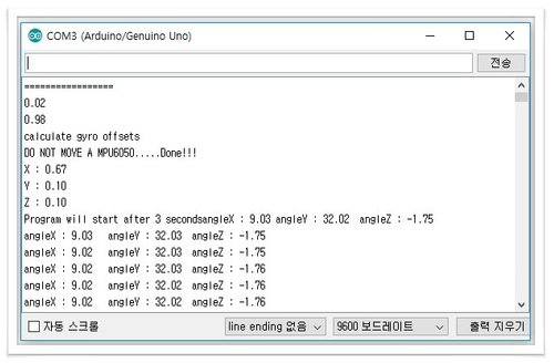
처음 한 번은 getAnglem 예제를 실행하여 아래와 같은 X, Y, Z값을 얻게 되면 그 값을 메모장에 적어놓아야 한다.

처음 getAngle 예제를 돌리면 (X, Y, Z)가 (0.67, 0.10, 0.10)으로 계산된다.
5천 번의 MPU-6050 모듈에 측정된 값을 계산하기 때문에 시간이 걸린다. 시작 위치의 초기값을 먼저 잡아놓으면 다음 계산이 필요 없기 때문에 빠르게 회전각을 얻을 수 있게 된다.
변경은 다음과 같은 calcGyroOffsets()을 주석처리하고 setGyroOffsets() 함수로 선언해 주면 된다. 아래의 X, Y, Z 값은 processing과 연결하여 실험할 당시의 X, Y, Z의 값이다. 실험하는 장소와 위치에서 처음 측정된 값으로 초기값으로 할 경우 이 수치는 달라진다.
mpu6050.setGyroOffsets(0.75, 0.05, 0.05);
어려 분들은 둘 중 하나를 선택해서 실험하시면 됩니다.
mpu6050.calcGyroOffsets(true); : 대기 시간이 길어지더라도 계산하겠면 선택
mpu6050.setGyroOffsets(0.75, 0.05, 0.05); : 처음 한 번만 계산해 놓고 그 값을 초기값으로 고정하겠다면 선택
2) processing 코딩
참고 : 조이스틱+processing 3D 도형 회전(1)(아두이노)
[참고 소스]
import processing.serial.*;
Serial myPort;
int x=0;
int y=0;
void setup() {
println(Serial.list());
myPort = new Serial(this, Serial.list()[0], 9600);
myPort.bufferUntil('\n');
noStroke();
size(600,600,P3D);
}
void draw() {
background(0); //배경색
lights(); //조명
pushMatrix(); //Start
fill(0,255,0); //채우기
translate(width/2,height/2,-100); //이동
rotateX(radians(y)); //x축 회전
rotateY(radians(x)); //y축 회전
box(200,100,200); //상자
popMatrix(); //End
}
void serialEvent(Serial p) {
String inString = myPort.readStringUntil('\n');
... 생략 ...
}
조이스틱으로 실험했던 일부 소스이다.
box를 x, y 회전을 시킨 소스의 일부분인데 오늘 사용할 부분만 제외하고 나머지 소스를 지웠다.
processing 문자열 읽기
void serialEvent(Serial p) {
String inString = myPort.readStringUntil('\n');
... 생략 ...
}
이렇게 코딩해서 시리얼통신에서 문자열일 들어오면 자동으로 이벤트 호출이 일어난다. 그리고 해당 시리얼포트로 문자열을 읽게 된다.
여기까지는 아두이노에서 코딩하는 방식과 같으나 processing에서는 링크 걸어놓은 String 방식으로 코딩을 하지 않고 간단하게 processing 함수를 이용하여 수정하도록 한다. split() 함수가 제공됨으로 쉽게 전체문자열에서 x, y, z 회전각을 분리해 낼 수 있다.
| String[] inStrings = split(inString, ','); |
inString으로 읽은 한 줄의 문자열에서 콤마(,)가 기준으로 쪼개진다. 그리고, 그 값은 문자열 배열 변수 inStrings에 저장되게 된다. 3개의 데이터를 전송하므로,
inStrings [0] => X축 회전
inStrings [1] => Y축 회전
inStrings [2] => Z 축 회전
이 값들이 저장되어 있게 된다. 하지만 이 값은 문자열이기 때문에 숫자형으로 변환해야 하는데 실수형 float()로 변환을 하면 다음과 같다.
| x=float(inStrings[0]); y=float(inStrings[1]); z=float(inStrings[2]); |
아두이노에서 시리얼통신으로 보내온 x, y, z값을 각각 실수형 x, y, z변수에 최종적으로 저장하게 된다.
void serialEvent(Serial p) {
String inString = myPort.readStringUntil('\n');
String[] inStrings = split(inString, ',');
x=float(inStrings[0]);
y=float(inStrings[1]);
z=float(inStrings[2]);
}
수신 String 중 회전각만 적용하기
문자열 읽기를 그냥 위와 같이 하면 에러가 발생한다.
그 이유는 MPU6050_tockn 라이브러리는 초기 세팅함수 안에는 다음과 같이 여러 문자열이 출력되기 때문이다.
회전 각이 나오기 전까지 여러 문장의 문자열이 출력되는데 단순 위 위와 같이 코딩하면 문제가 발생한다.
MPU6050_tockn라이브러리에 가서 cpp 파일에 해당 함수의 들어있는 print문을 전부 주석처리하면 해결할 수 있지만 회전각 문자열인지 체크하는 제어문을 넣어서 해결하도록 하겠습니다.
String inString = myPort.readStringUntil('\n');
int separator_ch = inString.indexOf(",");
if(separator_ch!=-1){
회전각 구하기;
}else{
print(inString);
}
이렇게 indexOf(', ')로 회전각 분리기호의 위치값을 찾는다. 회전각 문자열에는 분리기호가 있기 때문에 해당 0 이상의 숫자값을 갖게 됩니다. 하지만 해당 문자열에 분리기호가 없다면 '-1'이 반환된다. 이 원리를 이용해서 위와 같이 if문으로 분리기호가 있으면 방금 위에서 코딩한 문자열에서 회전각을 분리해 내는 로직을 붙이면 된다.
분리기호가 없다면 그냥 시리얼모니터 창으로 해당 문자열을 출력하게 하면 간단히 이 문제를 해결하게 된다.
box 회전시키기
box 회전을 하려면 이 부분을 수정해야 합니다. rotateX(), rotateY(), rotateZ() box 회전을 시키고 해당 인자값을 아까 String으로 읽은 값을 다음으로 설정한다.
rotateX(radians(y)); //x축 회전
rotateY(radians(x)); //y축 회전
rotateZ(radians(z)); //y축 회전
box(200,100,200); //상자
위 코드는 x, y, z 축으로 회전시켜서 box()을 배치하는 코딩이다.
box() 함수 앞에다가 회전함수를 넣으면 최종적으로 회전시킨 곳에 box가 그려지기 때문에 box가 x, y, z 값에 의해서 이동하는 것처럼 보이게 됩니다. 그리기 함수 부분은 아래와 같이 된다.
void draw() {
background(0); //배경색
lights(); //조명
pushMatrix(); //Start
fill(0,255,0); //채우기
translate(width/2,height/2,-100); //이동
rotateX(radians(y)); //x축 회전
rotateY(radians(x)); //y축 회전
rotateZ(radians(z)); //y축 회전
box(200,100,200); //상자
popMatrix(); //End
}
[processing 실험 소스]
import processing.serial.*;
Serial myPort;
float x=0;
float y=0;
float z=0;
void setup() {
println(Serial.list());
myPort = new Serial(this, Serial.list()[0], 19200);
myPort.bufferUntil('\n');
noStroke();
size(600,600,P3D);
}
void draw() {
background(0); //배경색
lights(); //조명
pushMatrix(); //Start
fill(0,255,0); //채우기
translate(width/2,height/2,-100); //이동
rotateX(radians(y)); //x축 회전
rotateY(radians(x)); //y축 회전
rotateZ(radians(z)); //y축 회전
box(200,100,200); //상자
popMatrix(); //End
}
void serialEvent(Serial p) {
String inString = myPort.readStringUntil('\n');
int separator_ch = inString.indexOf(",");
if(separator_ch!=-1){
String[] inStrings = split(inString, ',');
x=float(inStrings[0]);
y=float(inStrings[1]);
z=float(inStrings[2]);
print(x);
print('/');
print(y);
print('/');
println(z);
}else{
print(inString);
}
}
추가로, print문으로 정확히 분리되어 x, y, z값이 나오는지 확인하기 위해서 processing 시리얼 모니터로 출력시키는 코딩을 넣었다.
5. 실험 결과
MPU-6050 모듈을 움직일 때 PC로 녹화한 영상입니다.
MPU-6050 모듈을 움직일 때 processing의 box가 어떻게 움직이는지 폰을 촬영한 영상입니다.
'Arduino > [2] Arduino Module' 카테고리의 다른 글
| [Arduino Module] #25. Wemos D1 R32 (1) | 2024.04.08 |
|---|---|
| [Arduino Module] #24. 와이파이 모듈(NodeMcu/ESP8266) (0) | 2024.04.01 |
| [Arduino Module] #22. 레이저 발광 (0) | 2024.04.01 |
| [Arduino Module] #21. 조이스틱 모듈 (0) | 2024.04.01 |
| [Arduino Module] #20. 적외선 발광/수광 모듈 (1) | 2024.03.26 |


